Building a mechanical keypad from scratch
Zen mind, beginner's mind.
Keyboards are a fascinating topic. We interact with them on a daily basis without the need for a deep understanding of how they work. I consider myself a keyboard enthusiast, yet, I had never built one myself.
In order to not get lost in the rabbit hole of possibilities, I decided to give this side-project a very clear goal and time-frame:
Goal
Build a functional mechanical keypad with ~13 keys and custom firmware from scratch in one weekend. Build it in a way that it could be theoretically scaled up to a larger size without problems; i.e. don't wire each switch to a dedicated pin on the Teensy.
In this post, I document the process for myself and for anyone who's interested.
I feel like one more thing needs to be said here: When I studied physics, there was this notion going around that electronics was just applied physics and that any physicist could basically derive (and thus practically work with) all of electronics from just the four Maxwell equations. That is utter bullshit. I think electronics are far from trivial and I have tremendous respect for people who have a good understanding of it - with Maxwell equations or without. For me, the Maxwell equations didn't help a tiny bit building this keyboard.
Parts and tools
I'll list and link to things I have bought and/or used for this project. None of the vendors mentioned have paid me for this. Linking to them is for documentation purposes only and not an endorsement.
Some parts, were ordered from reichelt.de:
- 12 Cherry MX Clear switches
- 12 1N4148 Diodes (as recommended in this Geekhack message board post)
- 1 Teensy 4.1
Other stuff I had lying around, either at home or in the office:
- Keycaps (obviously...): I used some WASD blank keycaps that I had to spare
- Four spare motherboard standoffs and screws
- Header pins for the Teensy
- A 30-row breakout board
- 7 breadboard jumper wires (male)
- Some insulated wire
- PLA for the printer - thanks to Tobi
- Solder
Tools
- Soldering tools
- Soldering iron
- 3rd hand
- Fume extractor - thanks to Julian
- 3D printer (we have a CraftBot from RuhrSource in the office)
- Phillips screwdriver
- MacBook using platformio
- Micro USB cable
3D printing the case
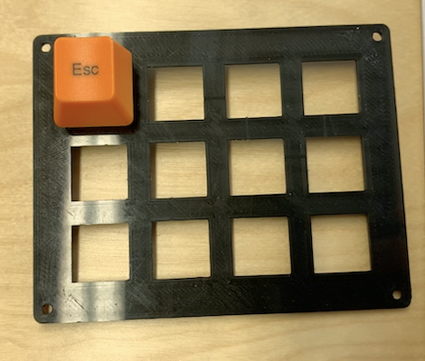
Originally, I wanted to include a rotary encoder and LEDs as well. However, given the time limit, I didn't want to spend a lot of the time learning Blender. So I decided to go with a simple layout from Thingyverse by user Laffy and not spend any time 3D modelling for the first version.
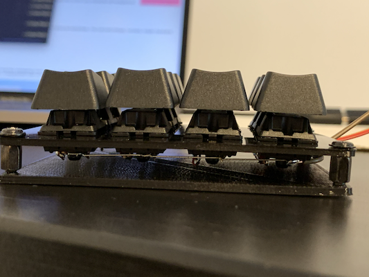
From there, printing was straightforward. I opened the STL files in CraftWare and sliced them on default settings for our printer. Didn't event look at the gCode and the results came out fine. The switches fit the holes nicely but don't quite click into place because the mount is slightly too thick. This will probably become a problem when trying to remove keycaps but it's okay for now.
Wiring
With only 12 keys and 42 digital pins on the Teensy, it would have been possible to just wire each switch to a dedicated pin. However, one goal of this project was to use a methodology that could scale up to larger boards. In a keyboard matrix circuit, the $k$ keys are arranged in a $m\times n$ matrix. This way, we only require $m + n$ instead of $k$ pins on the controller. The controller then has to scan that matrix row-by-row (or column-by-column) and collect the responses. E.g. if it gives current to row 1, it can figure out whether buttons $(1, 1), …, (1, n)$ are pressed by measuring the current on columns $1, …, n$.
I loosely followed these three guides:
- https://geekhack.org/index.php?topic=87689.0
- http://www.masterzen.fr/2018/12/16/handwired-keyboard-build-log-part-1/
- https://matt3o.com/hand-wiring-a-custom-keyboard/
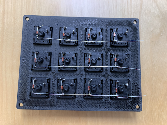
I used the diodes' legs to connect the rows. The diodes are used to prevent current flowing back through the switches. Thus, they effectively prevent ghosting. Have a look at the explanation in masterzen's blog post.
Then, I connected the columns using some litz wire. Here, I was trying to be clever and use a single piece of wire with holes in the insulation. The idea was that I could then connect the same wires to the controller.
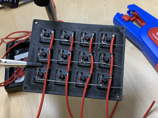
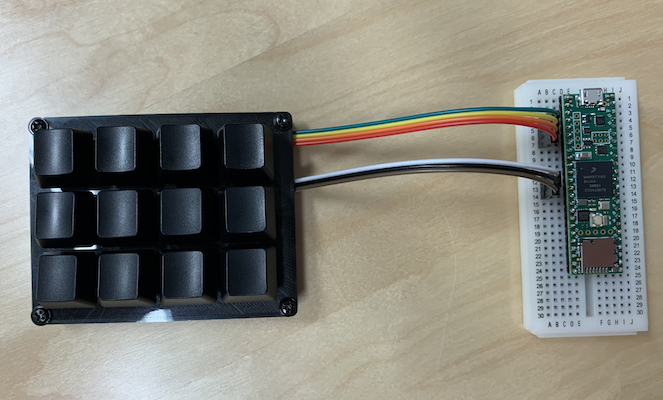
First of all, it was difficult to get the distances right. Then again, the wires were too stiff to be routed to the controller so I ended up cutting them anyway and wiring jumper wires to the columns, as well. Here's the final layout after attaching the jumper wires.
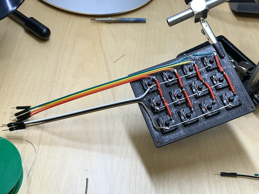
You'll notice that the wires go outside the case. Since I only had motherboard spacer screws at hand, I decided to keep the controller outside the case. This is not a problem for functionality but definitely something I'll change in the next iteration.
Soldering all this stuff was a pain and even though I used a fume extractor fan, my dinner tasted like solder, afterwards. Next time I'm going with a PCB.
Firmware
After all the soldering and worrying about whether the electronics will actually work, this was supposed to be the fun part. Of course, there is existing keyboard firmware on the internet, but I wanted to write my own.
First, I probed the matrix manually e.g. by setting all rows to OUTPUT and LOW and row 0 to HIGH and then measuring the response in the INPUT columns. There are a few things wrong with that, notably that one should use pull-up mode for the inputs (INPUT_PULLUP) and set rows to INPUT while they are not scanning. Because of the pull-up, we would then scan by setting the row to LOW.
Thanks to a great message board post that provided some debouncing code, I was able to get a first version running Saturday night. The important lesson here - at least for me who's more of a programmer anyway - is that since electronics are flaky (switches "bounce"), you cannot just treat a switch like a binary signal.
You can find the firmware on GitHub at kdungs/keyb. In the first version, it just maps each switch to a specific key. I'll spend the rest of this Sunday tweaking it and playing around with things like layers, chords, etc. You'll be able to find the results of that in said repo and if I stumble over anything cool, I'll also update this post.
Result
Lessons learned
Teensy doesn't show up as a device on the Mac, in fact as someone pointed out in a message board:
There are posts here explaining that teensy uses a special USB protocol for downloading. Only if the downloaded program uses Serial will a COM port (windows) appear. This confuses AVR Arduino newbies.
Hand-wiring is fun and interesting at first, but can be a real pain. I'm not sure, I would want to to this again for a full-size board. Next time around, I'll try out a PCB. However, I was surprised by how fault-tolerant the process turned out to be. I didn't expect my crappy soldering to work so well.
3D-printed stuff is nice but I don't know enough about it to make it work at high quality. So I either have to learn more about it or use laser-cut metal or something else the next time around.
What's next?
- Improve the firmware
- A better case that can house the Teensy
- Use the rotary encoder and LEDs!
Go to the corresponding issue on GitHub, in order to discuss this article.